Real project · DFM and fabrication
Aluminium panel: from a bending constraint to the finished part
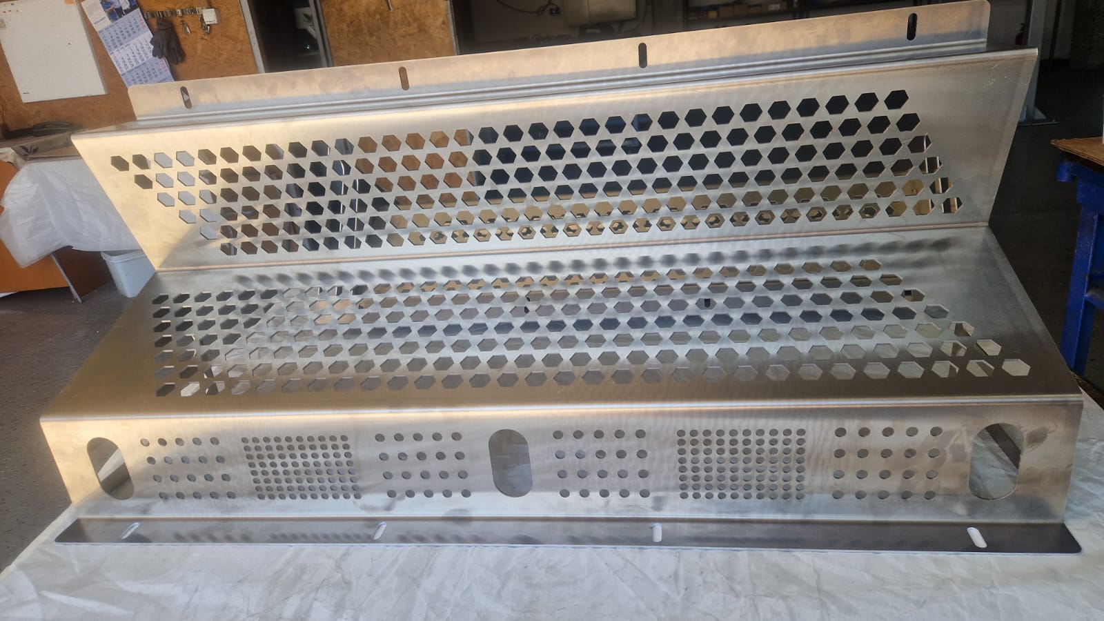
The customer wanted the part made in one piece. During bending, its geometry would have collided with the machine frame, with a risk of deformation. DFM analysis provided the starting point for the fabrication approach.
Have a challenging part to manufacture? We start with your geometry and requirements.
01 / The manufacturing challenge
Why could the part not be bent from a single piece?
In this project, the constraint was the interaction between the part geometry and the bending machine. With the design approach initially requested by the customer, the part would have struck the machine frame during bending. There was also a risk of deformation.
A CAD model must also be assessed against the operations needed to manufacture it. Here, DFM analysis identified a specific manufacturing constraint before attempting the single-piece approach.
A single piece
The customer wanted the geometry manufactured without dividing the part into separate elements.
Collision with the machine frame
The geometry interfered with the machine during bending. The risk of deformation had to be considered when choosing the manufacturing process.
Bending and welded assembly
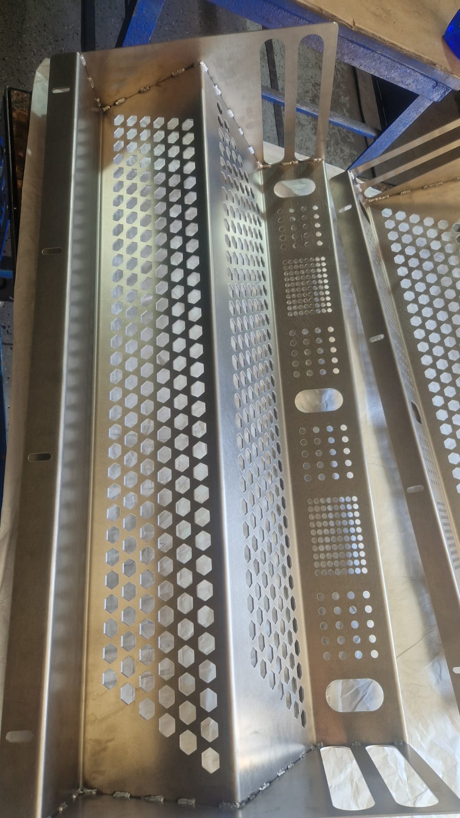
The two parts were manufactured using laser cutting, bending, and TIG and laser welding, followed by packaging.
02 / From CAD to the workshop
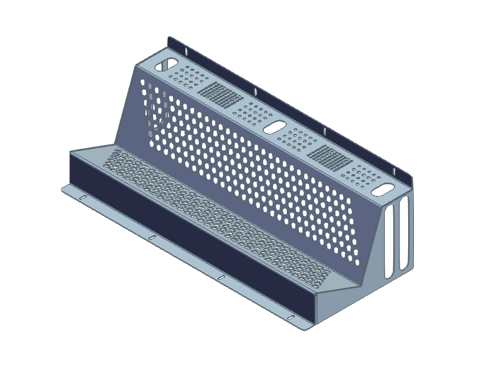
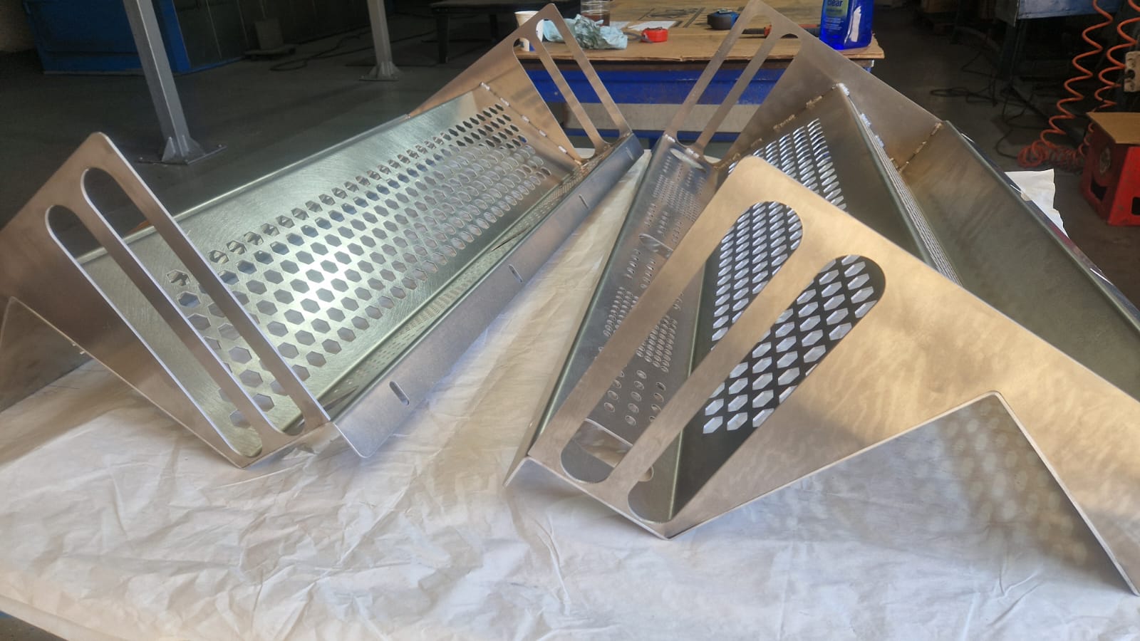
The model and the two manufactured parts
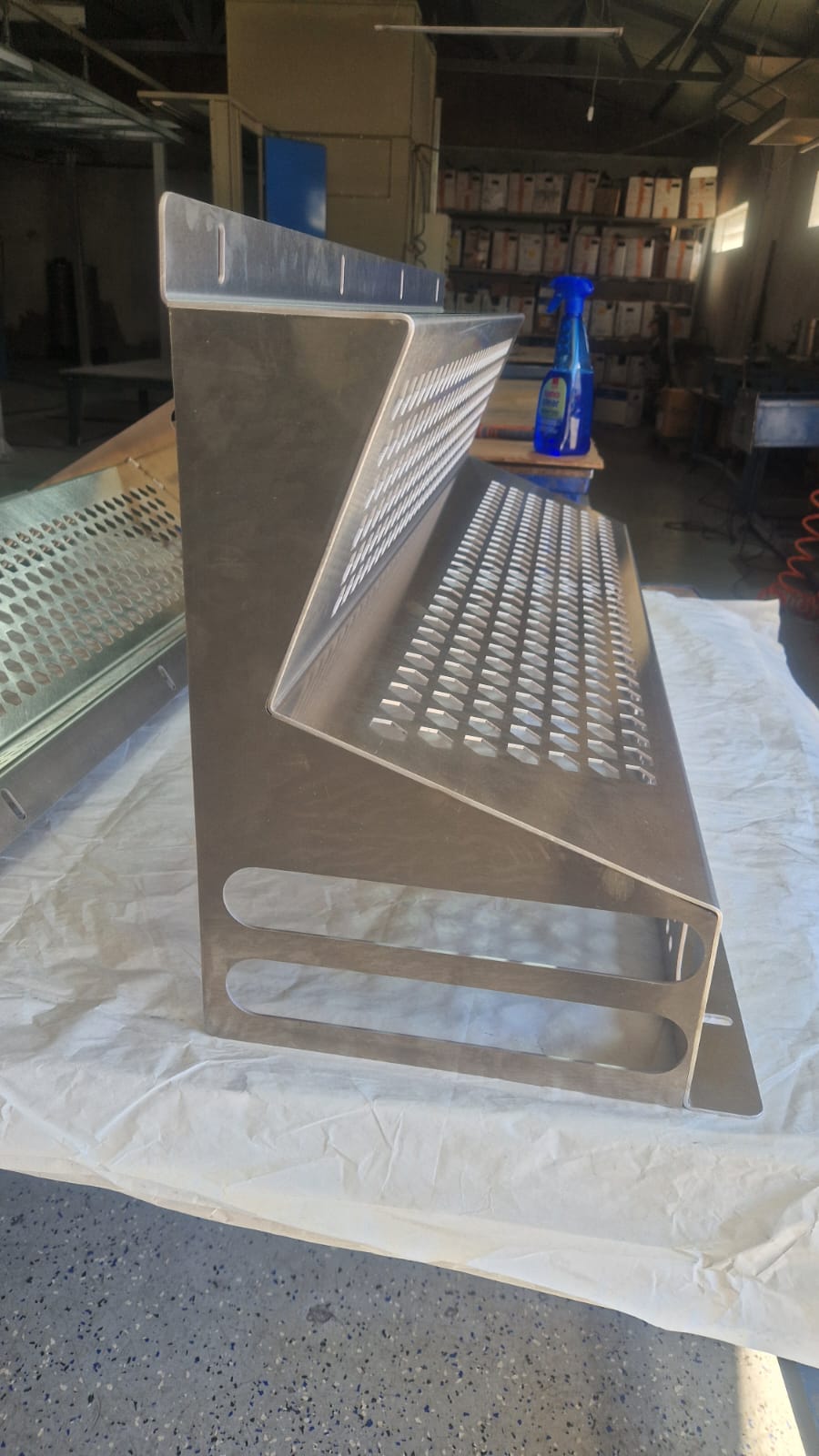
The photographs show the hexagonal and circular perforations, elongated cut-outs and side geometry of the manufactured parts.
03 / Technical data
Material, dimensions and operations
| Material | Aluminium EN AW-5754 / 3.3535 / AlMg3 |
|---|---|
| Sheet thickness | 2.5 mm |
| Overall CAD dimensions | 1010.0 × 444.45 × 327.22 mm |
| Specified volume | 1729.32 cm³ |
| Weight calculated from CAD | 4.787 kg |
| Quantity manufactured | 2 parts |
| Operations | DFM, laser cutting, bending, TIG and laser welding, packaging |
Dimensions and weight come from the CAD model, rather than final inspection measurements. The photographs document the manufactured parts and their packaging.
04 / Preparing for transport
The project continues through packaging
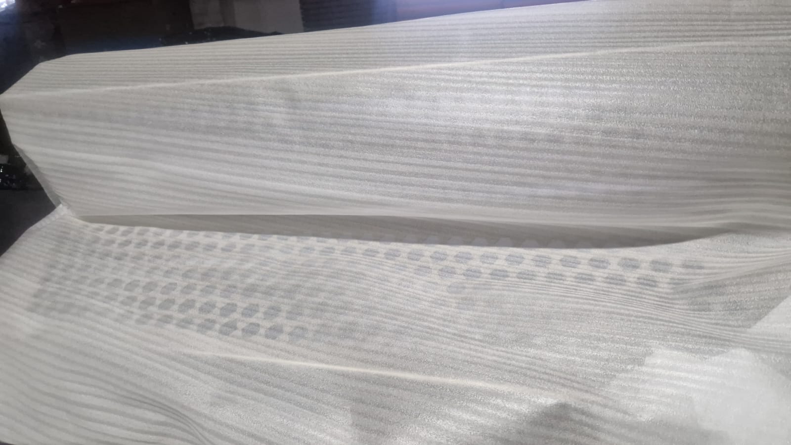
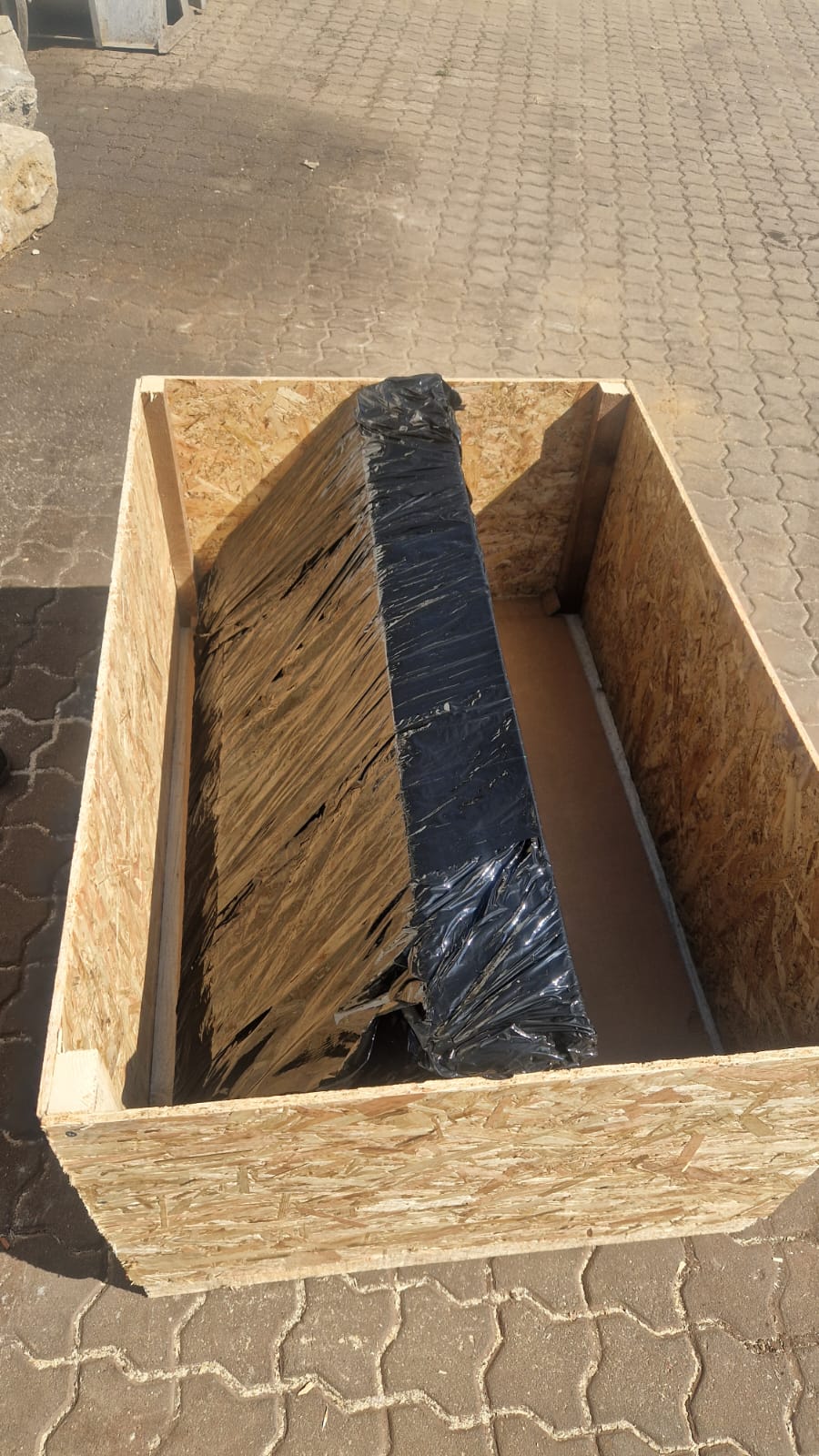
The parts were wrapped in protective material. The photographs also show protective film and packing in a crate.
Before you send your project
What does DFM mean for a sheet metal part?
DFM stands for Design for Manufacturing: assessing a design from a manufacturing perspective. In this case, the analysis identified a collision between the part and the machine frame during bending, as well as a risk of deformation with the single-piece approach.
Do I need to know how the part will be manufactured?
You can start the discussion with your CAD model and functional requirements. Specify which areas cannot be changed and whether welded joints are acceptable. This helps us discuss a manufacturing approach suited to your project.
Which files and information help us prepare a quote?
Send the STEP model and the technical drawing, if available. Include material, thickness, quantity, critical tolerances, finishing requirements and your requested delivery date. Mention any manufacturing difficulty already identified.
Can I discuss a project involving only a few parts?
Yes, you can send your requirements for assessment. The project shown here involved two parts. Feasibility, price and lead time are assessed for each project's geometry and requirements.
From a drawing to a practical discussion
Does your part look simple but prove difficult to manufacture?
Send us your CAD model and explain what the part needs to do. We can discuss manufacturing constraints and the operations required before preparing a quote.
What helps us understand your project
- The model and any available technical drawing.
- Material, thickness and quantity.
- Tolerances, critical areas and requested delivery date.
The button opens the HABA file upload form. Your model is not ready yet? Contact us.